# Holybro Durandal
:::warning
PX4 does not manufacture this (or any) autopilot.
Contact the [manufacturer](https://holybro.com/) for hardware support or compliance issues.
:::
_Durandal_® is the latest update to the successful family of Holybro flight controllers.
It was designed and developed by Holybro.

At high level, some of the key features are:
- Integrated temperature control for sensors.
- Powerful STM32H7 microcontroller running at 480MHz.
2 MB of Flash memory and 1 MB of RAM.
- New sensors with higher temperature stability.
- Internal vibration isolation system.
- Dual high-performance, low-noise IMUs on board are designed for demanding stabilization applications.
A summary of the key features, [assembly](../assembly/quick_start_durandal.md), and [purchase](#purchase) links can be found below.
::: info
This flight controller is [manufacturer supported](../flight_controller/autopilot_manufacturer_supported.md).
:::
## Quick Summary
#### Technical Specifications
- Main FMU Processor: STM32H743
- 32 Bit Arm ® Cortex® -M7, 480MHz, 2MB memory, 1MB RAM
- IO Processor: STM32F100
- 32 Bit Arm ® Cortex® -M3, 24MHz, 8KB SRAM
- On-board sensors
- Accel/Gyro: ICM-20689
- Accel/Gyro: BMI088 or ICM20602
- Mag: IST8310
- Barometer: MS5611
- GPS: u-blox Neo-M8N GPS/GLONASS receiver; integrated magnetometer IST8310
#### Interfaces
- 8-13 PWM servo outputs (8 from IO, 5 from FMU)
- 6 dedicated PWM/Capture inputs on FMU
- Dedicated R/C input for Spektrum / DSM
- Dedicated R/C input for CPPM and S.Bus
- Dedicated S.Bus servo output and analog / PWM RSSI input
- 5 general purpose serial ports
- 3 with full flow control
- 1 with separate 1.5A current limit
- 3 I2C ports
- 4 SPI buses
- 1 internal high speed SPI sensor bus with 4 chip selects and 6 DRDYs
- 1 internal low noise SPI bus dedicated for XXX
- Barometer with 2 chip selects, no DRDYs
- 1 internal SPI bus dedicated for FRAM
- Supports temperature control located on sensor module
- 1 external SPI buses
- Up to 2 CANBuses for dual CAN
- Each CANBus has individual silent controls or ESC RX-MUX control
- Analog inputs for voltage / current of 2 batteries
- 2 additional analog inputs
#### Electrical Data
- Power module output: 4.9~5.5V
- Max input voltage: 6V
- Max current sensing: 120A
- USB Power Input: 4.75~5.25V
- Servo Rail Input: 0~36V
#### Mechanical Data
- Dimensions: 80x45x20.5mm
- Weight: 68.8g
#### Other Characteristics
- Operating temperature: ~40~85C
- Storage temperature: -40~85C
- CE
- FCC
- RoHS compliant (lead-free)
For more information see: [Durandal Technical Data Sheet](https://cdn.shopify.com/s/files/1/0604/5905/7341/files/Durandal_technical_data_sheet_90f8875d-8035-4632-a936-a0d178062077.pdf).
## Where to Buy
Order from [Holybro](https://holybro.com/products/durandal).
## Connections
The locations of ports/connections are shown here (and below in the [pinouts section](#pinouts)).
### Top

### Front

### Back

### Right
### Left

## Dimensions
All dimensions are in millimeters.

## Assembly/Setup
The [Durandal Wiring Quick Start](../assembly/quick_start_durandal.md) provides instructions on how to assemble required/important peripherals including GPS, Power Management Board etc.
## Building Firmware
:::tip
Most users will not need to build this firmware!
It is pre-built and automatically installed by _QGroundControl_ when appropriate hardware is connected.
:::
To [build PX4](../dev_setup/building_px4.md) for this target:
```
make holybro_durandal-v1_default
```
## Serial Port Mapping
| UART | Device | Port |
| ------ | ---------- | ------------- |
| USART1 | /dev/ttyS0 | GPS1 |
| USART2 | /dev/ttyS1 | TELEM1 |
| USART3 | /dev/ttyS2 | TELEM2 |
| UART4 | /dev/ttyS3 | TELEM4/GPS2 |
| USART6 | /dev/ttyS4 | TELEM3 |
| UART7 | /dev/ttyS5 | Debug Console |
| UART8 | /dev/ttyS6 | PX4IO |
## Debug Port {#debug_port}
The [PX4 System Console](../debug/system_console.md) and [SWD interface](../debug/swd_debug.md) run on the _Debug Port_.
The pinouts and connector comply with the [Pixhawk Debug Mini](../debug/swd_debug.md#pixhawk-debug-mini) interface defined in the [Pixhawk Connector Standard](https://github.com/pixhawk/Pixhawk-Standards/blob/master/DS-009%20Pixhawk%20Connector%20Standard.pdf).
For wiring and debugging information see the above links.
::: info
No Debug port is exposed for the I/O board.
:::
## Peripherals
- [Digital Airspeed Sensor](https://store-drotek.com/793-digital-differential-airspeed-sensor-kit-.html)
- [Telemetry Radio Modules](../telemetry/index.md)
- [Rangefinders/Distance sensors](../sensor/rangefinders.md)
## Supported Platforms / Airframes
Any multicopter / airplane / rover or boat that can be controlled with normal RC servos or Futaba S-Bus servos.
The complete set of supported configurations can be seen in the [Airframes Reference](../airframes/airframe_reference.md).
## Pinouts
_Durandal_ pinouts are listed below.
These can also be downloaded from [here](https://cdn.shopifycdn.net/s/files/1/0604/5905/7341/files/Durandal_Pinouts_v1.0.pdf?v=1693983344).
### Top Pinouts

### Front Pinouts

#### SUBS Out port
| Pin | Signal | Volt |
| ---------- | ---------------- | ----- |
| 1 (red) | - | - |
| 2 (yellow) | SBUS_OUT/RSSI_IN | +3.3V |
| 3 (black) | GND | GND |
#### DSM RC port
| Pin | Signal | Volt |
| ---------- | ------- | ----- |
| 1 (red) | VDD_3V3 | +3.3V |
| 2 (yellow) | DSM_IN | +3.3V |
| 3 (black) | GND | GND |
#### I2C A port
| Pin | Signal | Volt |
| --------- | ------ | ----- |
| 1 (red) | VCC | +5V |
| 2 (black) | SCL4 | +3.3V |
| 3 (black) | SDA4 | +3.3V |
| 4 (black) | GND | GND |
#### CAN1 port
| Pin | Signal | Volt |
| --------- | ------ | ----- |
| 1 (red) | VCC | +5V |
| 2 (black) | CAN H | +3.3V |
| 3 (black) | CAN L | +3.3V |
| 4 (black) | GND | GND |
#### GPS port
| Pin | Signal | Volt |
| ---------- | ----------------- | ----- |
| 1 (red) | VCC | +5V |
| 2 (black) | TX (out) | +3.3V |
| 3 (black) | RX (in) | +3.3V |
| 4 (black) | SCL1 | +3.3V |
| 5 (black) | SDA1 | +3.3V |
| 6 (black) | SAFETY_SWITCH | +3.3V |
| 7 (black) | SAFETY_SWITCH_LED | +3.3V |
| 8 (black) | VDD_3V3 | +3.3V |
| 9 (black) | BUZZER | +5V |
| 10 (black) | GND | GND |
#### TELEM4 I2CB ports
| Pin | Signal | Volt |
| --------- | -------- | ----- |
| 1 (red) | VCC | +5V |
| 2 (black) | TX (out) | +3.3V |
| 3 (black) | RX (in) | - |
| 4 (black) | SCL2 | - |
| 5 (black) | SDA2 | +3.3V |
| 6 (black) | GND | GND |
#### TELEM3, TELEM2, TELEM1 port
| Pin | Signal | Volt |
| --------- | --------- | ----- |
| 1 (red) | VCC | +5V |
| 2 (black) | TX (out) | +3.3V |
| 3 (black) | RX (in) | +3.3V |
| 4 (black) | CTS (in) | +3.3V |
| 5 (black) | RTS (out) | +3.3V |
| 6 (black) | GND | GND |
#### POWER port
| Pin | Signal | Volt |
| --------- | ------- | ----- |
| 1 (red) | VCC | +5V |
| 2 (black) | VCC | +5V |
| 3 (black) | CURRENT | +3.3V |
| 4 (black) | VOLTAGE | +3.3V |
| 5 (black) | GND | GND |
| 6 (black) | GND | GND |
### Back Pinouts

#### MAIN Out
| Pin | Signal | Volt | + | - |
| --- | ------ | ----- | --------- | --- |
| 1 | IO_CH1 | +3.3V | VDD_SERVO | GND |
| 2 | IO_CH2 | +3.3V | VDD_SERVO | GND |
| 3 | IO_CH3 | +3.3V | VDD_SERVO | GND |
| 4 | IO_CH4 | +3.3V | VDD_SERVO | GND |
| 5 | IO_CH5 | +3.3V | VDD_SERVO | GND |
| 6 | IO_CH6 | +3.3V | VDD_SERVO | GND |
| 7 | IO_CH7 | +3.3V | VDD_SERVO | GND |
| 8 | IO_CH8 | +3.3V | VDD_SERVO | GND |
#### AUX Out
| Pin | Signal | Volt | + | - |
| --- | ------- | ----- | --------- | --- |
| 1 | FMU_CH1 | +3.3V | VDD_SERVO | GND |
| 2 | FMU_CH2 | +3.3V | VDD_SERVO | GND |
| 3 | FMU_CH3 | +3.3V | VDD_SERVO | GND |
| 4 | FMU_CH4 | +3.3V | VDD_SERVO | GND |
| 5 | FMU_CH5 | +3.3V | VDD_SERVO | GND |
#### RC IN
| Pin | Signal | Volt |
| --- | -------------- | ----- |
| S | SBUS_IN/PPM_IN | +3.3V |
| + | VCC | +5V |
| - | GND | GND |
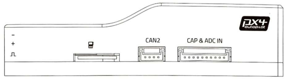
### Right-side Pinouts

#### CAN2 port
| Pin | Signal | Volt |
| --------- | ------ | ----- |
| 1 (red) | VCC | +5V |
| 2 (black) | CAN H | +3.3V |
| 3 (black) | CAN L | +3.3V |
| 4 (black) | GND | GND |
#### CAP & ADC IN port
| Pin | Signal | Volt |
| ---------- | ------------ | ------------------------ |
| 1 (red) | VCC | +5V |
| 2 (black) | FMU_CAP6 | +3.3V |
| 3 (black) | FMU_CAP5 | +3.3V |
| 4 (black) | FMU_CAP4 | +3.3V |
| 5 (black) | FMU_CAP3 | +3.3V |
| 6 (black) | FMU_CAP2 | +3.3V |
| 7 (black) | FMU_CAP1 | +3.3V |
| 8 (black) | ADC1_SPARE_1 | +3.3V [++](#warn_sensor) |
| 9 (black) | ADC1_SPARE_2 | +6.6V [++](#warn_sensor) |
| 10 (black) | GND | GND |
:::warning
\++ Sensors connected to pins 8, 9 must not send a signal exceeding the indicated voltage.
:::
### Left-side Pinouts

#### DEBUG port
| Pin | Signal | Volt |
| --------- | ------ | ----- |
| 1 (red) | VT | +3.3V |
| 2 (black) | TX | +3.3V |
| 3 (black) | RX | +3.3V |
| 4 (black) | SWDIO | +3.3V |
| 5 (black) | SWCLK | +3.3V |
| 6 (black) | GND | GND |
#### SPI port
| Pin | Signal | Volt |
| --------- | ------ | ----- |
| 1 (red) | VCC | +5V |
| 2 (black) | SCK | +3.3V |
| 3 (black) | MISO | +3.3V |
| 4 (black) | MOSI | +3.3V |
| 5 (black) | CS1 | +3.3V |
| 6 (black) | CS2 | +3.3V |
| 7 (black) | GND | GND |
#### USB port
| Pin | Signal | Volt |
| --------- | ------ | ----- |
| 1 (red) | VBUS | +5V |
| 2 (black) | DM | +3.3V |
| 3 (black) | DP | +3.3V |
| 4 (black) | GND | GND |
## Further info
- [Durandal Wiring QuickStart](../assembly/quick_start_durandal.md)
- [Durandal Technical Data Sheet](https://cdn.shopify.com/s/files/1/0604/5905/7341/files/Durandal_technical_data_sheet_90f8875d-8035-4632-a936-a0d178062077.pdf)
- [Durandal Pinouts](https://cdn.shopifycdn.net/s/files/1/0604/5905/7341/files/Durandal_Pinouts_v1.0.pdf?v=1693983344) (Holybro)